|
La paradossale implementazione di test - La matrice di LED "Visual Braille" - The paradoxical test implementation - The "Visual Braille" LED matrix
|
|
|
Ancor prima di descrivere l'idea, vorrei dire che so che avrei dovuto e voluto fare di meglio. |
Even before describing the idea, I'd like to state that I know that I should and would have done better. |
|
|
|
|
Problemi principali: |
Main problems: |
|
|
|
|
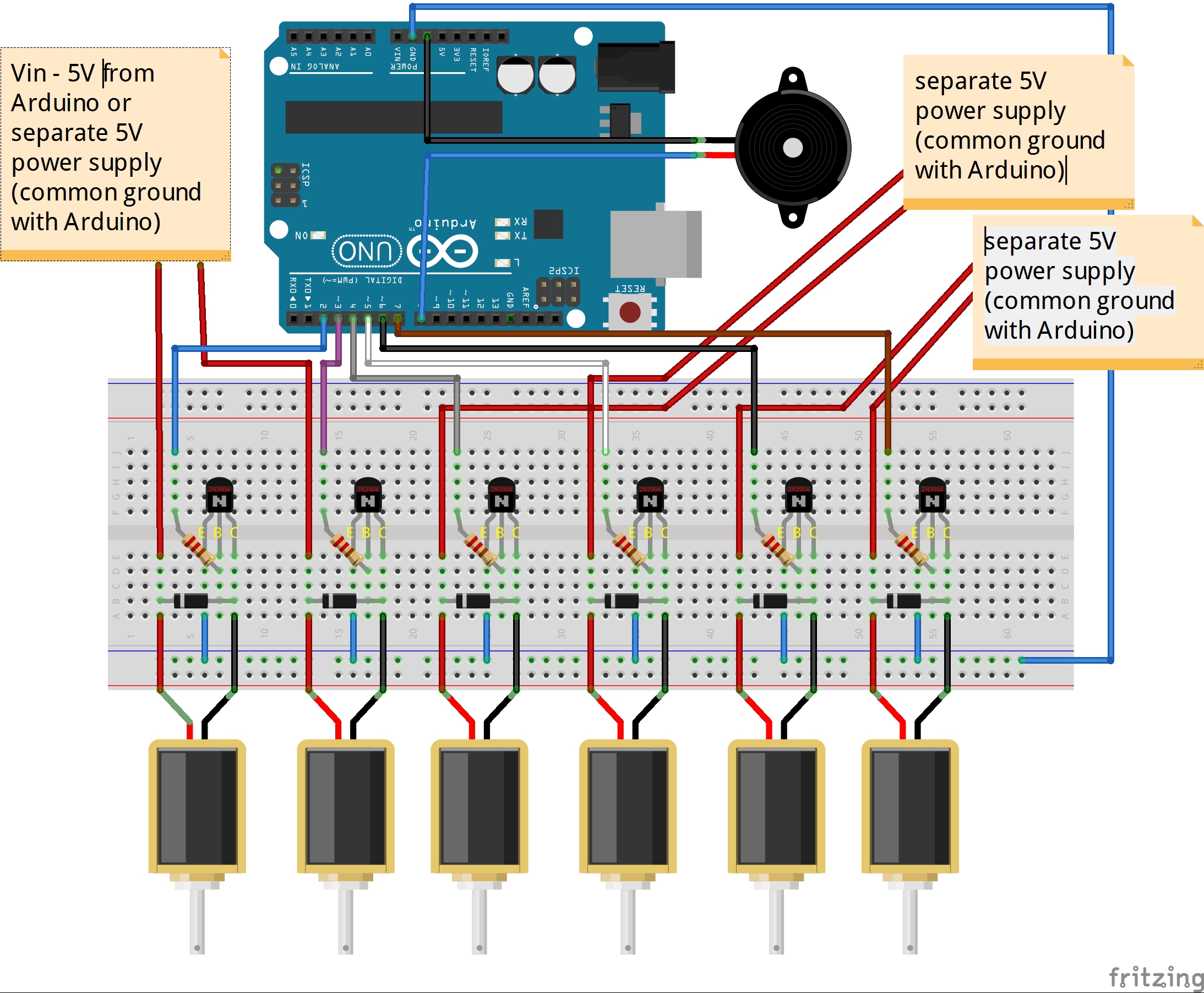
2) Non avrei dovuto essere preoccupato di usare solenoidi da 12V o 9V. Quando ho acquistato i più economici 5V, era anche per poter alimentare tutto con i classici 5V di Arduino (ignoravo ancora il problema di assorbimento di corrente dei solenoidi). |
2) I shouldn't have been worried to use 12V or 9V solenoids. When purchasing the cheapest 5V ones, I wanted to power everything with the classic 5V from Arduino (I still ignored the current absorption problem of the solenoids). |
|
|
|
|
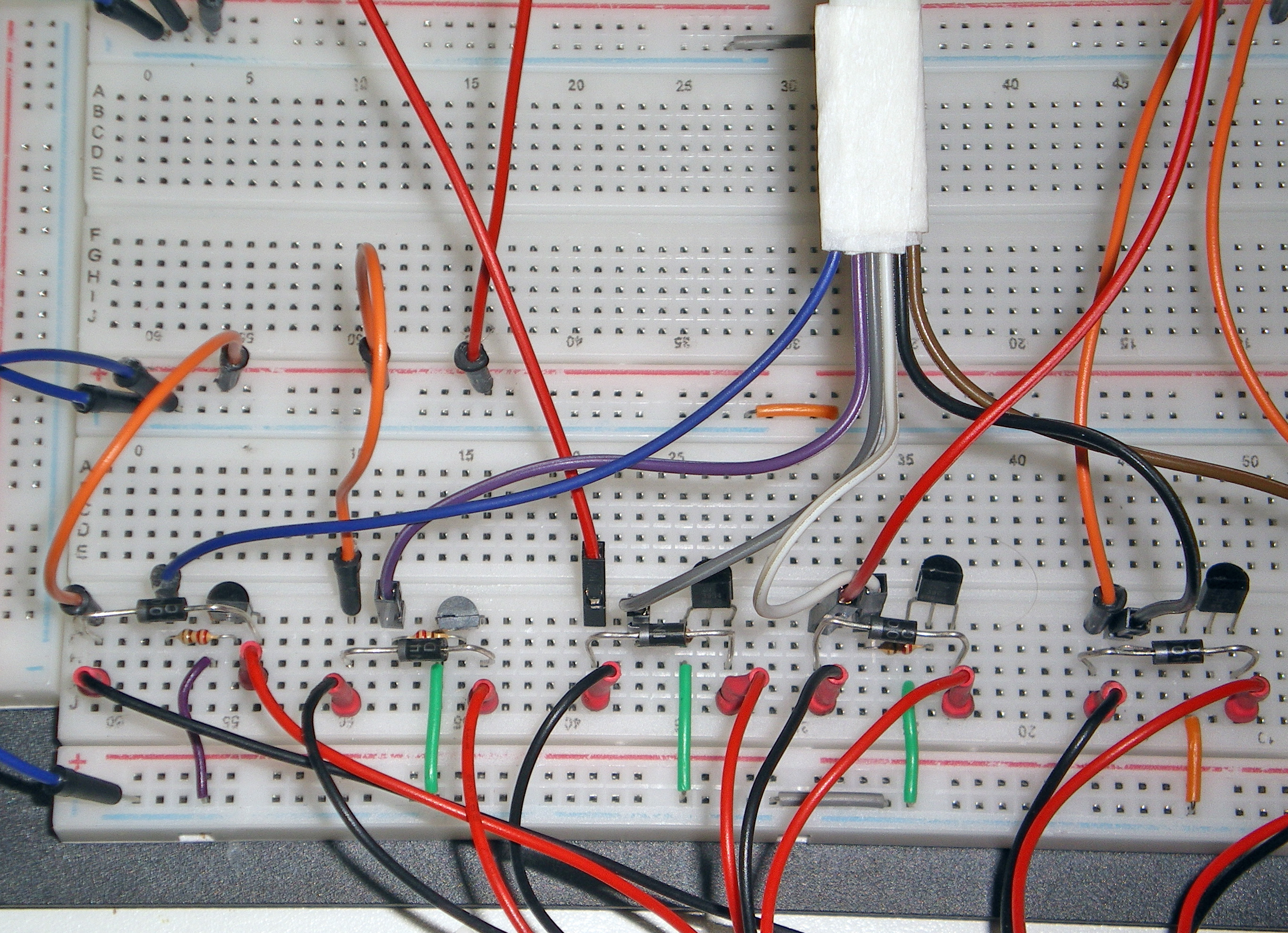
3) Corrente: i solenoidi, anche i 5V più piccoli e più economici che ho usato, sono dispositivi assetati. Qualsiasi tentativo di alimentare più di due solenoidi con Vin o 5V da Arduino si traduce in reset continui, a causa dell'assorbimento eccessivo di corrente dei solenoidi. Anche con alimentazione separata ai solenoidi, se la potenza è al limite, sono frequenti i mancati azionamenti. |
3) Current: solenoids, even the smallest and cheapest 5V that I used, are thirsty devices. Any attempt to power more than two solenoids with Vin or 5V from Arduino results in continuous resets, due to the excessive current absorption by the solenoids. Even with separate power to the solenoids, if power is marginal, misfires are frequent. |
|
|
|
|
Ecco una lista di buone implementazioni di solenoidi + Arduino: https://www.google.com/search?tbs=li%3A1&q=arduino+solenoids&oq=arduino+solenoids - vedi in particolare https://arduino.stackexchange.com/questions/50668/can-arduino-control-8-solenoids per una buona consulenza tecnica. |
Here is a list of good implementations of solenoids + Arduino: https://www.google.com/search?tbs=li%3A1&q=arduino+solenoids&oq=arduino+solenoids - see in particular https://arduino.stackexchange.com/questions/50668/can-arduino-control-8-solenoids for good technical advice. |
|
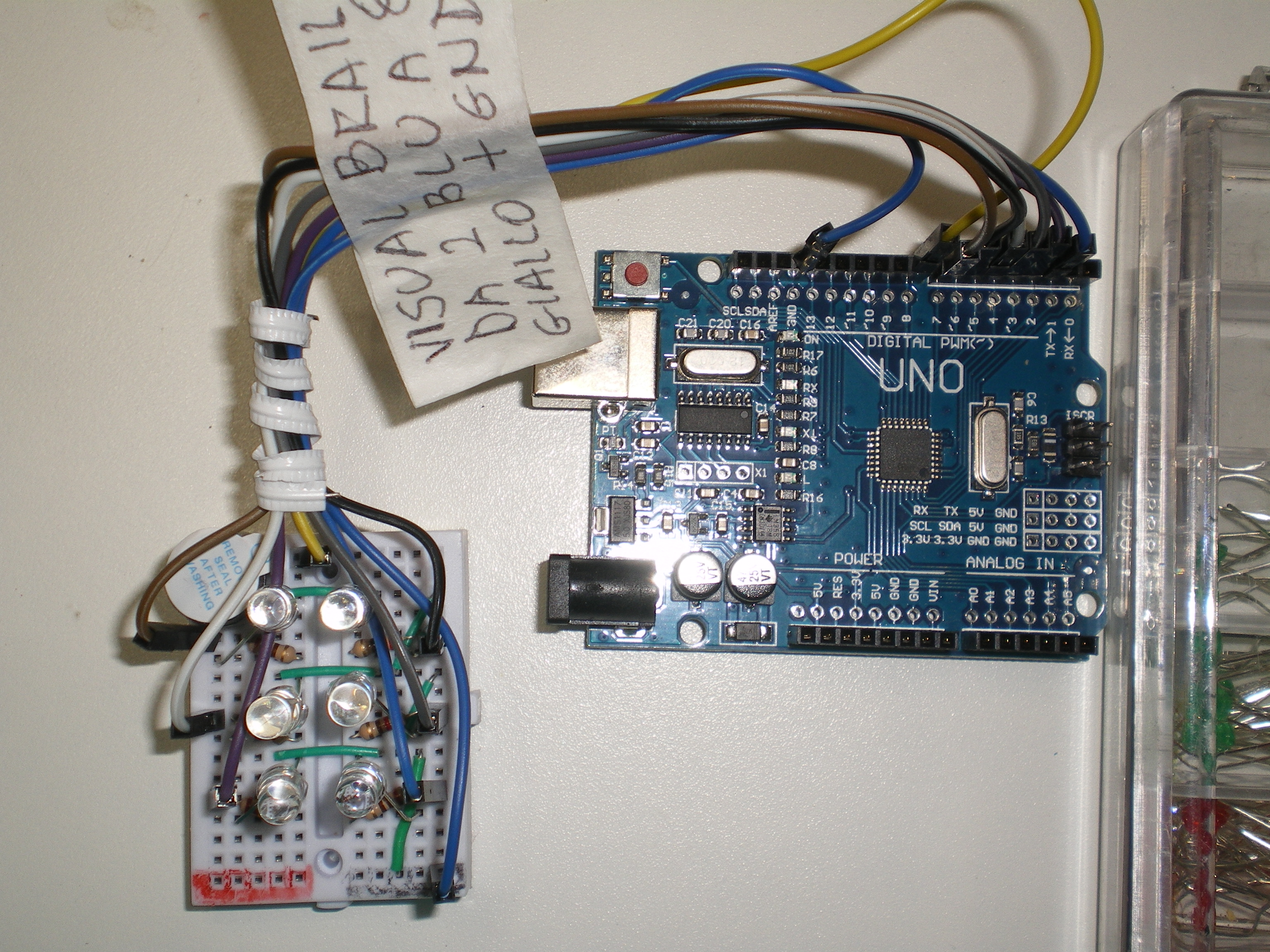
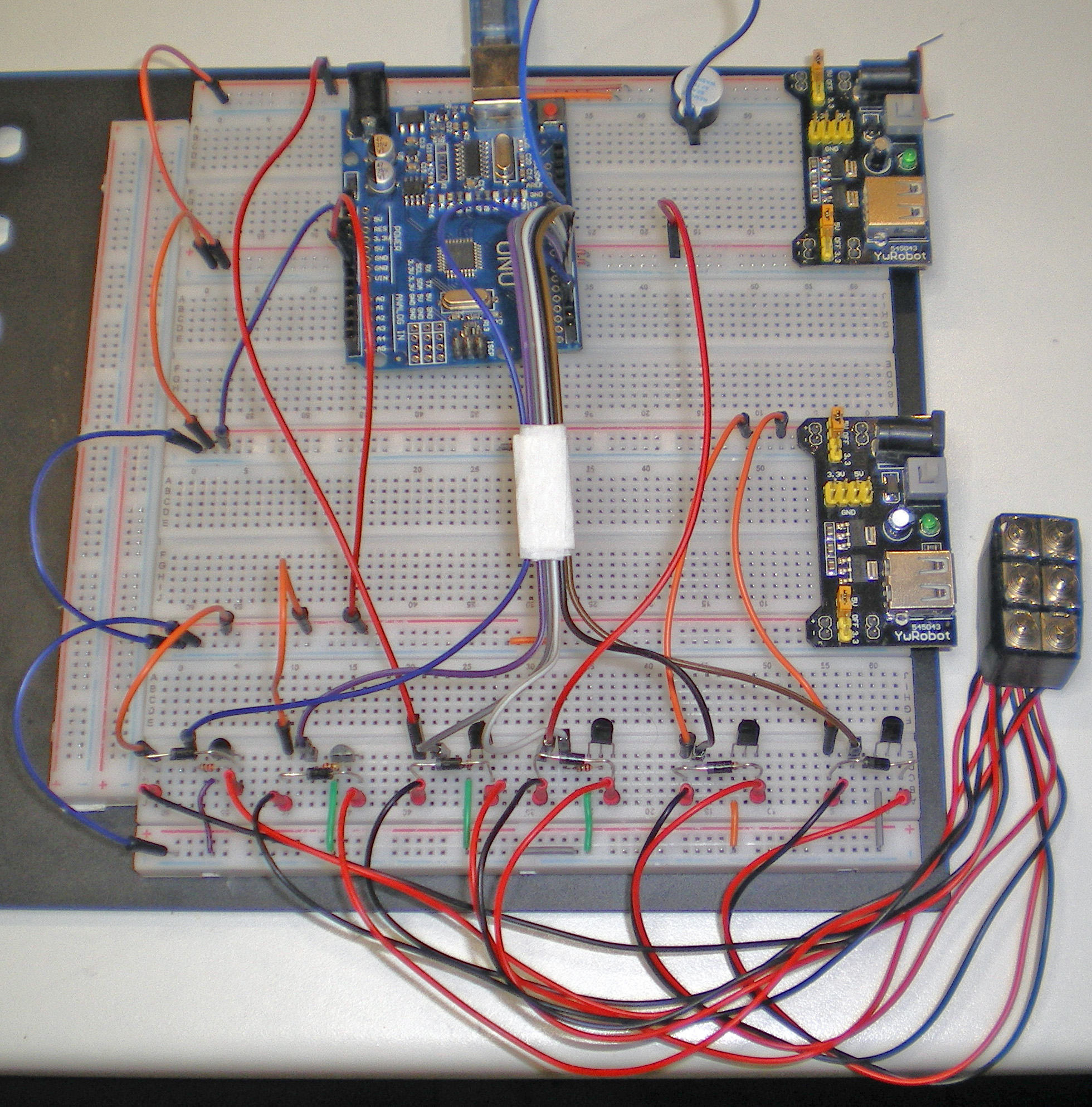
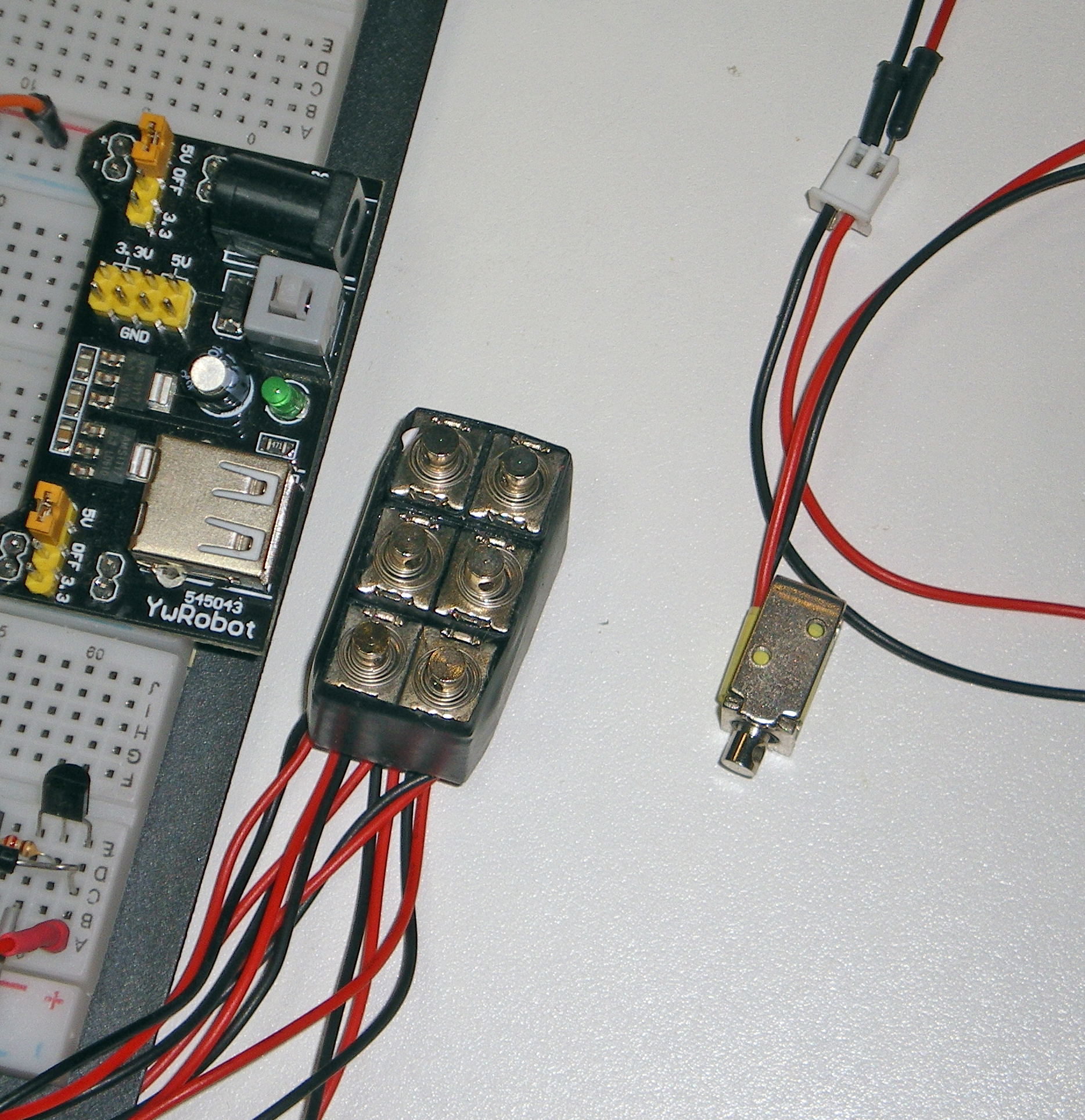
FUNZIONAMENTOCon i solenoidi disposti in un pacco 3x2 come illustrato (ciascun solenoide è stato avvolto individualmente con nastro isolante, quindi in file e in un unico blocco), l'obiettivo sarebbe quello di far fuoriuscire / estrarre il nucleo di ciascun solenoide se il rispettivo punto è attivato. E ciò funzionerebbe egregiamente con i *veri* solenoidi push-pull, che scatterebbero fuori decisamente e poi di nuovo dentro dopo essere stati disattivati.In pratica, con il circuito e i componenti illustrati e con tutto alimentato a 5 V, anche con alimentazioni separate i solenoidi si muovono a mala pena (a meno che gli alimentatori non siano impostati a una tensione superiore... il che potrebbe non essere sicuro!) Ma, con il polpastrello del pollice premuto delicatamente sulla punta dei pistoni, si può comunque percepire quali punti si alzano e quali punti sono immobili. Se un pistone si sgancia e viene espulso, deve essere fatto nuovamente premuto all'interno fino allo scatto: un altro inconveniente di questa attrezzatura subottimale. Grazie per l'attenzione! |
OPERATIONWith the solenoids arranged in a 3x2 pack as illustrated (each solenoid was individually wrapped in insulating tape, then again in rows and in a single block), the objective would be to have the core of each solenoid pop out /stick out if its respective point is activated. And that would work egregiously with *real* push-pull solenoids, that would pop out decidedly then pop in as soon as inactivated.In fact, with the illustrated circuit and components, and with everything powered at 5V, even with separate power supplies the solenoids barely move (unless power supplies are set at an higher voltage... that may be unsafe!) but, with the thumb's pad gently pressed on the tips of the pistons, one may anyway perceive which tips are being rised and which tips are motionless. If one piston disengages and is ejected, it must be clicked in again: another drawback of this suboptimal equipment. Thanks for the attention! |
|
|
|
|
COMPONENTIAttenzione! La realizzazione di un array di solenoidi completamente funzionante potrebbe richiedere una riprogettazione integrale, e un set differente di componenti.
Il progetto su Arduino Project Hub Grazie per l'attenzione! |
COMPONENTSWarning! The realization of a fully operational solenoid array may require a complete redesign, and a different set of components.
The project on Arduino Project Hub Thanks for the attention! |
/*
Arduino ASCII- Braille Translator
by Cesare Brizio | CC by-sa-nc
this sketch is in the public domain
Version 1.0 - 29 June 2019
------------------------------
This sketch will use six small solenoids/electromagnets arranged in
three rows of two columns to operate a Braille dot matrix.
Any ASCII character sent to Arduino via COM port will be "translated"
in a timed sequence of Braille symbols by configuring, one character
at a time, the dot matrix, so that the "dots" (solenoids) corresponding
to the current ASCII character are raised for 500 msec before passing to
the subsequent character.
When an un-translatable character is sent, a short buzz is emitted.
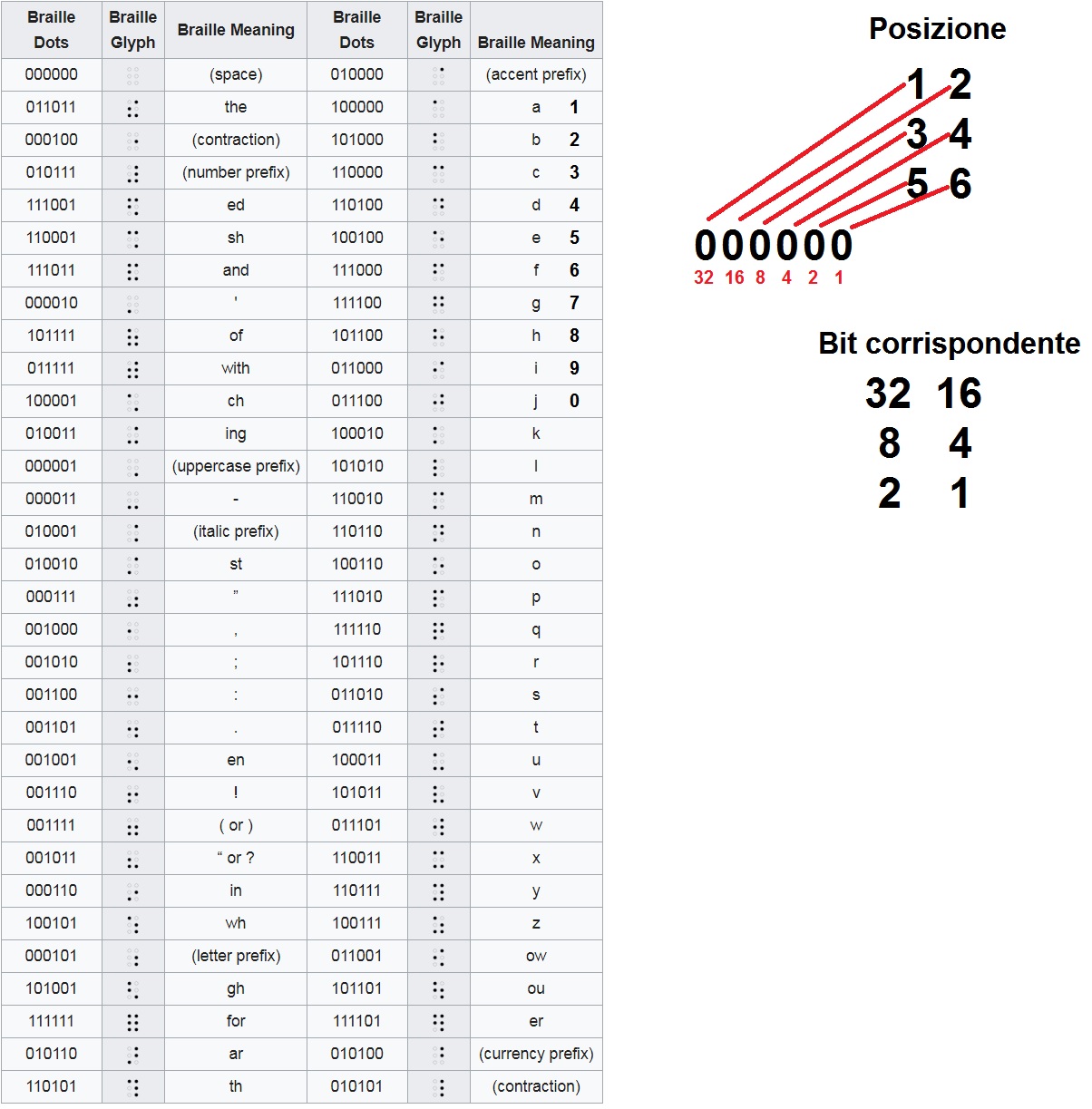
==== DOT NUMBERING ====
Dots are not numbered according to the Braille convention, but are
conventionally numbered from left to right, then from top to bottom:
1 2
3 4
5 6
As an example, showing letter "b" (asterisk represent an high dot):
*-
*-
--
will require raising dots number 1 and 3
==== DOT CONFIGURATION ====
Dot configuration will be stored as a series of six binary values. As an example,
according to the preceding explanation, the configuration for "b" is 101000.
As long as configurations contain just 6 bits of information, they can be stored
in a single char that, translated bitwise (least significant bit at right), corresponds
to the needed configuration.
So, 101000 (configuration for "b"), corresponding to DEC 40 and HEX 28, will be
represented by ASCII character "(".
Summarizing, considering that ascii code for "b" is 98D (62H) I will say that
myBrailleDots[98] = 40;
that is equivalent to
myBrailleDots[98] = '(';
meaning that the binary sextet corresponding to letter "b" is 101000.
When needed, a bitwise AND with increasing powers of two (from 1 to 32) will reveal
which dots shall be raised: this is accomplished by iterating through a 6 bit mask:
Some simplifications will be applied, e.g.:
a) the multi-letter Braille glyphs (ch, ing, for, ar, th and others)
b) number prefix (010111),
c) letter prefix (000101),
d) uppercase prefix (000001) and other prefixes
will not be implemented in this version, but this sketch can
be quite easily implemented with the needed modifications.
*/
// Declare a char array with one index for every possible ASCII byte / character
byte myBrailleDots[255];
int firstOutputPin = 2; // pin corresponding to least significant bit
int buzzerPin = 8; // Buzzer on pin 8
byte matrixPoints = 0; // byte that will store the point matrix configuration
// for a specific ASCII character
byte inByte;
byte mask = 1; //our bitmask
void setup() {
// Temporarily assign 99 to every possible ASCII byte/character
// All the characters in the input string will decode to "99" by default
for (int i = 0; i < 256; i = i + 1) {
myBrailleDots[i] = 99;
}
// Now, only for the ASCII characters with a corresponding Braille character.
// assign the corresponding Braille Dot configuration
myBrailleDots[32] = 0; // blank is 000000
myBrailleDots[33] = 14; // exlamation mark is 001110
myBrailleDots[34] = 7; // double quote is 000111
myBrailleDots[34] = 2; // single quote is 000010
myBrailleDots[40] = 15; // left parenthesis is 001111
myBrailleDots[41] = 15; // right parenthesis is 001111
myBrailleDots[44] = 8; // comma is 001000
myBrailleDots[46] = 13; // period is 001101
myBrailleDots[48] = 28; // 0 is 011100
myBrailleDots[49] = 32; // 1 is 100000
myBrailleDots[50] = 40; // 2 is 101000
myBrailleDots[51] = 48; // 3 is 110000
myBrailleDots[52] = 52; // 4 is 110100
myBrailleDots[53] = 36; // 5 is 100100
myBrailleDots[54] = 56; // 6 is 111000
myBrailleDots[55] = 60; // 7 is 111100
myBrailleDots[56] = 44; // 8 is 101100
myBrailleDots[57] = 24; // 9 is 011000
myBrailleDots[58] = 12; // colon is 001100
myBrailleDots[59] = 10; // semicolon is 001010
myBrailleDots[63] = 11; // question mark is 001011
myBrailleDots[65] = 32; // A is 100000
myBrailleDots[66] = 40; // B is 101000
myBrailleDots[67] = 48; // C is 110000
myBrailleDots[68] = 52; // D is 110100
myBrailleDots[69] = 36; // E is 100100
myBrailleDots[70] = 56; // F is 111000
myBrailleDots[71] = 60; // G is 111100
myBrailleDots[72] = 44; // H is 101100
myBrailleDots[73] = 24; // I is 011000
myBrailleDots[74] = 28; // J is 011100
myBrailleDots[75] = 34; // K is 100010
myBrailleDots[76] = 42; // L is 101010
myBrailleDots[77] = 50; // M is 110010
myBrailleDots[78] = 54; // N is 110110
myBrailleDots[79] = 38; // O is 100110
myBrailleDots[80] = 58; // P is 111010
myBrailleDots[81] = 62; // Q is 111110
myBrailleDots[82] = 46; // R is 101110
myBrailleDots[83] = 26; // S is 011010
myBrailleDots[84] = 30; // T is 011110
myBrailleDots[85] = 35; // U is 100011
myBrailleDots[86] = 43; // V is 101011
myBrailleDots[87] = 29; // W is 011101
myBrailleDots[88] = 51; // X is 110011
myBrailleDots[89] = 55; // Y is 110111
myBrailleDots[90] = 39; // Z is 100111
myBrailleDots[97] = 32; // A is 100000
myBrailleDots[98] = 40; // B is 101000
myBrailleDots[99] = 48; // C is 110000
myBrailleDots[100] = 52; // D is 110100
myBrailleDots[101] = 36; // E is 100100
myBrailleDots[102] = 56; // F is 111000
myBrailleDots[103] = 60; // G is 111100
myBrailleDots[104] = 44; // H is 101100
myBrailleDots[105] = 24; // I is 011000
myBrailleDots[106] = 28; // J is 011100
myBrailleDots[107] = 34; // K is 100010
myBrailleDots[108] = 42; // L is 101010
myBrailleDots[109] = 50; // M is 110010
myBrailleDots[110] = 54; // N is 110110
myBrailleDots[111] = 38; // O is 100110
myBrailleDots[112] = 58; // P is 111010
myBrailleDots[113] = 62; // Q is 111110
myBrailleDots[114] = 46; // R is 101110
myBrailleDots[115] = 26; // S is 011010
myBrailleDots[116] = 30; // T is 011110
myBrailleDots[117] = 35; // U is 100011
myBrailleDots[118] = 43; // V is 101011
myBrailleDots[119] = 29; // W is 011101
myBrailleDots[120] = 51; // X is 110011
myBrailleDots[121] = 55; // Y is 110111
myBrailleDots[122] = 39; // Z is 100111
pinMode(buzzerPin, OUTPUT);
pinMode(2, OUTPUT);
pinMode(3, OUTPUT);
pinMode(4, OUTPUT);
pinMode(5, OUTPUT);
pinMode(6, OUTPUT);
pinMode(7, OUTPUT);
Serial.begin(9600);
Serial.println("ASCII - Braille Arduino Converter");
Serial.println("LED test - begin");
digitalWrite(2,HIGH);
digitalWrite(3,HIGH);
digitalWrite(4,HIGH);
digitalWrite(5,HIGH);
digitalWrite(6,HIGH);
digitalWrite(7,HIGH);
delay(3000);
digitalWrite(2,LOW);
digitalWrite(3,LOW);
digitalWrite(4,LOW);
digitalWrite(5,LOW);
digitalWrite(6,LOW);
digitalWrite(7,LOW);
Serial.println("LED test - end");
Serial.println("Type some character: it will be transmitted to Arduino and displayed on a Braille 2 x 3 matrix");
}
void loop() {
// Braille print data only when you receive data:
if (Serial.available() > 0) {
// read the incoming byte:
inByte = Serial.read();
// say what you got:
Serial.print("Received (inByte): ");
Serial.println(inByte);
// Translate inByte in matrix points
Serial.print("Matrix points variable (myBrailleDots[inByte]): ");
Serial.println(myBrailleDots[inByte]);
// Braille print only admissible characters
// the unadmissible ones decode to 99
if (myBrailleDots[inByte] == 99) // if unadmissible
{
Serial.println("Not a translatable character");
digitalWrite(buzzerPin,HIGH); // buzz
delay(250);
digitalWrite(buzzerPin,LOW); // stop buzzing
}
else{
int thisPin = 2;
for (mask = 000001; mask<64; mask <<= 1) {
Serial.print("thisPin = ");
Serial.println(thisPin);
if (myBrailleDots[inByte] & mask){ // if bitwise AND resolves to true
Serial.print("AND successful, put pin on!");
Serial.println(mask);
digitalWrite(thisPin,HIGH);
}
else{ //if bitwise and resolves to false
Serial.print("AND unsuccessful, put pin off!");
Serial.println(mask);
digitalWrite(thisPin,LOW);
}
thisPin = thisPin + 1;
}
}
delay(3000); // allow 3 sec before passing to next character
}
}
❦